FPGA Lab: High-Speed Oscillator LED Blinker
Introduction
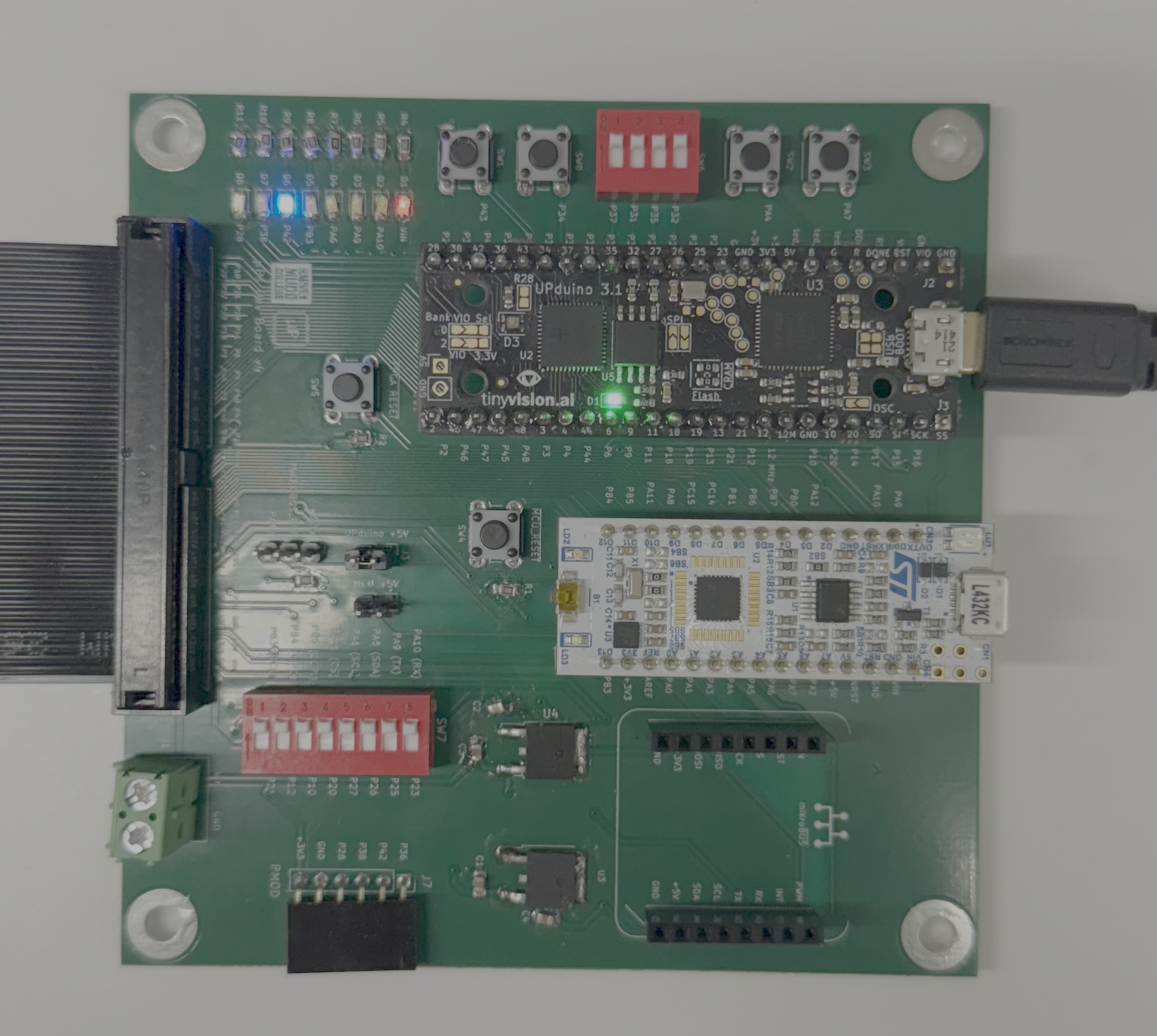
Figure 1: Shows the Microprocessor Development Board v.4 with the Upduino FPGA and MCU, along with pushbuttons and switches.
In this lab, a design was implemented on the FPGA to demonstrate the functionality of the on-board high-speed oscillator by blinking one of the on-board LEDs on the development board (shown in Figure 1). The high-speed oscillator was configured at a frequency of 48 MHz and divided down using a counter to achieve a blinking frequency of 2.4 Hz.
Design and Testing Methodology
We assembled the E155 development board by soldering SMT and THT components, followed by verifying voltage regulators (3.3V and 5V). Testing involved loading a pre-written FPGA design to blink LEDs and then programming the MCU to read and echo signals. Once verified, we wrote our own Verilog modules to interface DIP switches with LEDs and a 7-segment display, synthesizing the design in Lattice Radiant and simulating with Questa ModelSim. Git was used to track project source code files.
The on-board high-speed oscillator (HSOSC) from the iCE40 UltraPlus primitive library was used to generate a clock signal at 24 MHz. Then, a counter was used to divide the high-frequency clock signal down so that the blinking frequency could be easily visualized using one of the on-board LEDs.
FPGA Design
On the E155 FPGA board, the inputs and outputs are organized around the switches, LEDs, and 7-segment display. The four DIP switches s[3:0] serve as user inputs, letting you select binary values that feed into the logic of the design. The three LEDs led[2:0] provide simple output indicators: led[0] and led[1] respond to combinations of the switch inputs, while led[2] blinks at a steady rate using the FPGA’s internal 48 MHz oscillator. Finally, the seven outputs seg[6:0] drive the segments of a common anode 7-segment display, which decodes the switch settings into a numeric pattern from to 0 to F.
| Signal Name | Type | Details |
|---|---|---|
[3:0] s |
input | DIP switches (SW6) |
[2:0] led |
output | LEDs (found on P42, P38, and P28) |
[6:0] seg |
output | common anode outputs on 7-segment display |
In regards to the LEDs, led[2] blinks at a frequency of 2.4Hz while led[0] switches on based a XOR relationship with s[0] and s[1] and led[1] swithes on based on AND relationship with s[2] and s[3].
Here is the following truth table:
[3:0]s |
[2:0]led |
[6:0]seg |
|---|---|---|
| 0000 | 000 | 0000001 |
| 0001 | 001 | 1001111 |
| 0010 | 001 | 0010010 |
| 0011 | 000 | 0000110 |
| 0100 | 000 | 1001100 |
| 0101 | 001 | 0100100 |
| 0110 | 001 | 0100000 |
| 0111 | 000 | 0001111 |
| 1000 | 000 | 0000000 |
| 1001 | 001 | 0001100 |
| 1010 | 001 | 0001000 |
| 1011 | 000 | 1100000 |
| 1100 | 010 | 0110001 |
| 1101 | 011 | 1000010 |
| 1110 | 011 | 0110000 |
| 1111 | 010 | 0111000 |
Technical Documentation
The source code for the project can be found in the associated GitHub repository.
Block Diagram
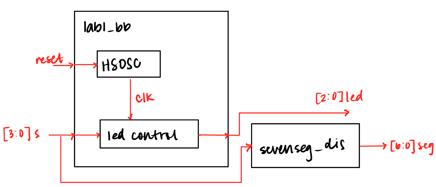
Figure 2: Block diagram of the Verilog design.
The block diagram in Figure 1 demonstrates the overall architecture of the design. The top-level module lab1_bb includes two submodules: the high-speed oscillator block (HSOSC) and the 7 segement display sevenseg_dis.
Schematic
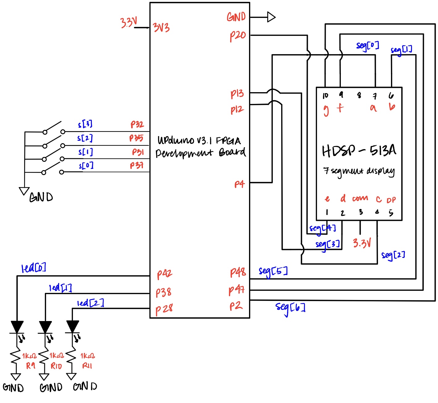
Figure 3: Schematic of the physical circuit of the FPGA, LEDs, switches and the 7-segment display.
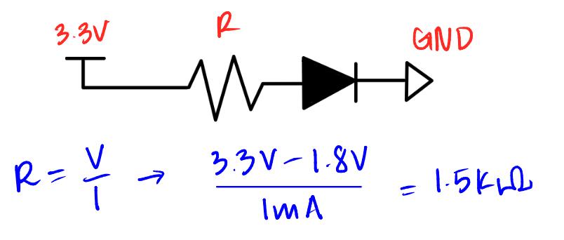
Figure 4: Show the internal wire from the FPGA to the 7-segment display.
This shows the physical layout of the design. An internal 1.5 kΩ pull-up resistor was used to ensure the active-low reset pin was not floating. The current running through the diode of the seven segment display (~1 mA) was divided by the Vcc subtracted by the forward voltage of a red LED.
Results and Discussion
The design met all intended design objectives through our testbench simulations.
Testbench Simulation
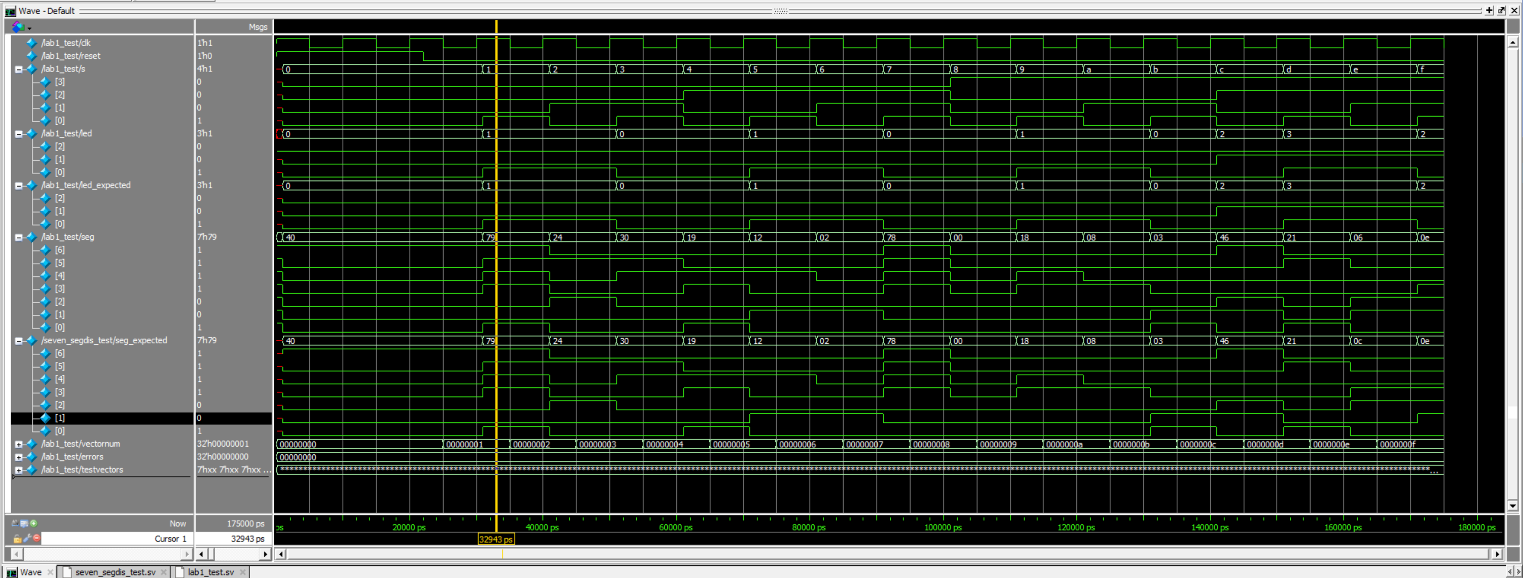 Figure 5: Screenshot of a QuestaSim simulation demonstrating the blinking output signal.
Note that the timescale for the clock divider was modified to divide by 4. If a more precise output frequency was desired, a more sophisticated counter could be developed. The current design only allows for the clock to be divided by powers of two. (MIGHT GET RID OF)
Oscilliscope of Blinking LED
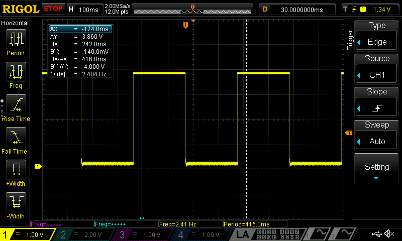
Figure 6: Screenshot of a oscilliscope waveform validating the exact frequency of 2.41 Hz.
Conclusion
The design successfully blinked an external LED using the on-board high-speed oscillator. I spent a total of 10+ hours working on this lab.
AI Prototype Summary
When conducting the AI prototype summary, the LLM I utilized was Microsoft’s Copilot. I prompted it to “Write SystemVerilog HDL to leverage the internal high-speed oscillator in the Lattice UP5K FPGA and blink an LED at 2 Hz, using idiomatic SystemVerilog. Copilot produced a short module that instantiated the UP5K high-speed oscillator, divided the clock with a counter, and drove an LED. The style was pretty clean for the counter. However, when I pasted it into a fresh Lattice Radiant project and hit Synthesize, Radiant failed immediately with a syntax error: Copilot had dropped a closing parenthesis in the oscillator instantiation and missed a semicolon at the end of a localparam line. After I copied Radiant’s error text back into Copilot, it regenerated the block with the missing ) and ; added. With those fixed, the synthesis was completed.
I would rate Copilot’s output as “good scaffolding, needs verification.” It nailed the overall structure and used modern SystemVerilog constructs I like adopting. It also wrote a clear reset path for the counter. None of those were brand-new to me, but it was helpful to see them composed neatly in a minimal example. If I did this again, I would tighten my workflow in three ways:
Treat the LLM as a code generator, not an authority. I’ll immediately run the output, then feed exact tool errors back to the model for focused corrections.
Ask the LLM to “emit compile ready, tool-specific primitives” and include a checklist in the prompt. That nudge seems to reduce trivial mistakes.
Add a quick unit sanity check in the prompt: “Assume ~48 MHz HFOSC; show the counter width/math to reach ~2 Hz.” That forces the model to spell out the divide math, which is convenient to verify before synthesis.